Methane - natural gas in Australia
Methane - natural gas in Australia
Occurences of methane - natural gas in Australia
Drilling Basics
Direction / Horizontal Drilling
Bitweight, Torque and Friction
Fracking
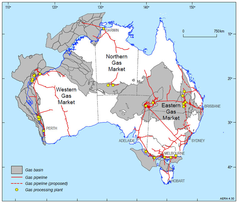
source: Geoscience Australia
Occurences of Methane in Australia
Natural gas is a combustible mixture of hydrocarbon gases. It consists mainly of methane (CH4), with varying levels of heavier hydrocarbons and other gases such as carbon dioxide. Naturalgas is formed by the alteration of organic matter. This can be by biogenic or thermogenic processes. When accumulated in a subsurfacereservoir that can be readily produced it is known as conventional gas.
Crude Oil and Methane gas CH4 are have been historically extracted from folded , domed or faulted geological structures called oil traps these are described elsewhere on this site.
Conventional gases (gas) fields can be dry (almost pure methane)or wet (associated with the “wet gas” components – ethane, propane, butanes and condensate). Dry gas has less energy contentthan wet gas. Conventional gas can also be found with oil in oil fields. Natural gas also occurs in more difficult to extractunconventional deposits, such as coal beds (coal seam gas), or in shales (shale gas), low quality reservoirs (tight gas), or as gashydrates.
Liquid Natural Gas (LNG) is primarily composed of the lightesthydrocarbons, methane (CH4) and ethane (C2H6); it is a gas at surface conditions but is cooled and compressed to aliquid for transport in LNG tankers to export markets. LNG is natural gas that is cooled to around -160oC until it forms a liquid, making it easier to transport.
Australia has significant gas resources, with gas beingAustralia’s third largest energy resource after coal and uranium. Conventional gas resources are widespread both on and offshore,occurring in fourteen different basins, but most of the resource is off the north-west margin in the Bonaparte, Browse and Carnarvonbasins.
https://www.ga.gov.au/scientific-topics/energy/resources/petroleum-resources/gas
Coal Seam Gas (CSG) is a naturally occurring methane gas found inmost coal seams and is similar to conventional natural gas. In Australia the commercial production of CSG commenced in 1996 in theBowen Basin, Queensland. Since then production has increased rapidly, particularly during the first decade of the 21st century. CSG has nowbecome an integral part of the gas industry in eastern Australia, particularly in Queensland.
Information about reserves of CSG has grown significantly,particularly in the Bowen and Surat basins in Queensland. In New South Wales reserves have been proven in the Sydney, Gunnedah,Clarence-Moreton and Gloucester basins. Exploration has been undertaken or is planned to be undertaken in other coal basinsincluding the Galilee, Arckaringa, Perth and Pedirka basins.
https://www.ga.gov.au/scientific-topics/energy/resources/petroleum-resources/coal-seam-gas
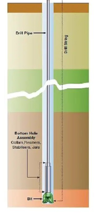
Drilling Basics
A drill string consists of a drill bit which rotates and cuts the rock and a drillstring, a series of rods that attach to the drill bit. You add more rods as the drill cuts deeper.In theory if drill bits rotate perfectly on a central axis, the direction of advancedoes not change.
Things that affect drill hole direction
- rocks are not uniformly hard in all directions so the drill hole
tends to deviate (change direction)
- the cutting action of the drill bit begins on the outside edge
and cuts inward, a clockwise rotation will tend to deviate right and
counter clockwise rotation deviate left.
- If left uncorrected the vertical drill hole will gradually
shallow, go increasingly less vertical and more horizontal and
follow a sort of corkscrew path.
- Hole collaring presents the highest risk of misalignment in the
drilling cycle. When collaring, the bit is not supported, so it
tends to “skate” across the surface. Uneven rock surfaces cause
bending stresses and the potential for the bit to tilt off-center.
- Excessive feed pressure causes the string to bend, thus tilting
the bit off-center. The downward force of the string weight and feed
pressure cause the bit to pivot during rotation. This motion
continuously forces the bit to one side of the hole, resulting in
deviation.
- In banded ground (successive hard and soft layers), the bit tends
to turn into the softer layers. In fractured ground, the bit tends
to follow the path of least resistance and follow fissures.
- Correct choice of rods or bits can help reduce hole deviation.

https://engineeringinsider.org/horizontal-drilling-working/
Directional / Horizontal Drilling
Horizontal drilling combined with fracking has facilitated the extraction of methane gasfrom deposits located in extensive but relatively thin horizontal geological strata.The hole deviation problem is more pronounced with horizontal holes. Gravity createssagging in the center of the string, pointing the bit upward and forcing it to rotate off-center. In addition, the weight of thestring causes the bit to pivot. Combined with counter-clockwise rotation, the bit is continuously forced to the left side of the holeand tends to wander up and left.
Horizontal drilling is simply a drilling process which allows you to drill at differentangles. It works with a bend near the bottom of the drill string near the bit with the help of steerable mud motor.
Clever technology is employed in order to get a vertical drill hole to deviate underprecise control to a horizontal orientation within the correct geological strata.
The steps used are
- the rotation of the drill string is stopped
- drilling “mud” is pumped under pressure down the near the end of
drill string
- by directing the mud a moveable section of string can be made to
“bend” a couple of degrees
- in addition the pressurised “mud” rotates a “mud motor” which is
a turbine apparatus inside the drill pipe just above the bit
- the rotating turbine turns just the drill bit and not the drill
string
- as the bit cuts the drill string is pushed from the surface and
“slides” along behind the bit
- the orientation of the hole is frequently monitored by devices on
the drill string
- the process then adjusted and repeated between string rotations,
bit rotation and altering the direction of the “bend”
Mud Motor
Drilling mud causes turbine to rotate which turns to bit but keeps the string stationary
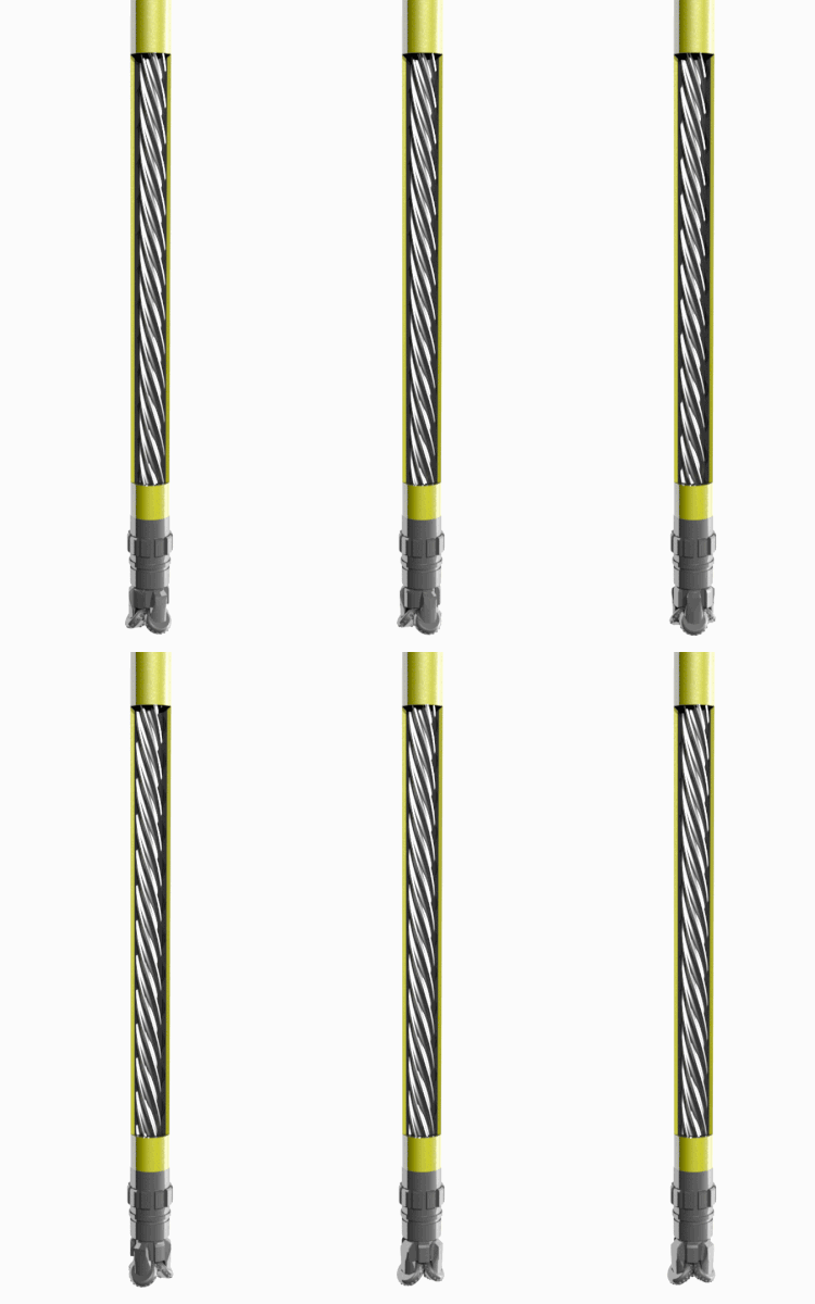
https://upload.wikimedia.org/wikipedia/commons/thumb/5/5c/Powersection%28PC_Pump%29.gif/250px-Powersection%28PC_Pump%29.gif
Bitweight, Torque and Friction
Controlling the direction of drill hole requires achieving a balance between.
- Bitweight – how much pressure you are exerting on the bit
- Torque – the speend of rotation of the string and bit or just the
bit
- Friction – the “drag “ of contact of the drill parts with the
surrounding abrasive rocks
source:https://www.slb.com/-/media/files/oilfield-review/04-slide-drilling-english
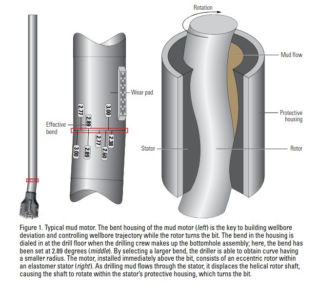
A bend in the motor bearing housing is key to steering the bit toward its target. The surface-adjustable bend can be set between 0° and 3°. This slight bend is sufficient for pointing the bit in a given direction yet is small enough to permit rotation of the entire mud motor assembly during rotary drilling. This seemingly minor deflection determines the rate at which the motor builds angle to establish a new wellbore trajectory. By orienting that bend in a specific direction, called its toolface angle, the driller can change the inclination and azimuth of the well path. To maintain the orientation of that bend and thus change wellbore trajectory, the drillstring must not be allowed to rotate, and this is where the mud motor comes into play. A mud motor is a type of positive displacement motor powered by drilling fluid. An eccentric helical rotor and stator assembly drive the mud motor (Figure 1). As it is pumped downhole, drilling fluid flows through the stator and turns the rotor. The mud motor converts hydraulic power to mechanical power to turn a drive shaft that causes the bit to rotate .
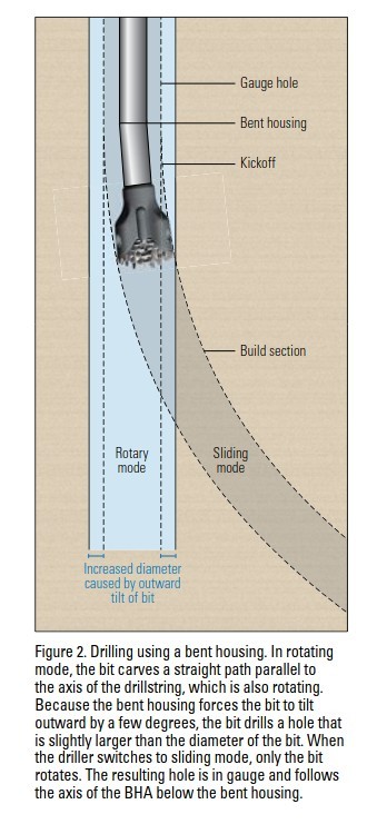
Using mud motors, directional drillers alternate between rotating and sliding modes of drilling. In rotating mode, the drilling rig’s rotary table or topdrive rotates the entire drillstring to transmit power to the bit. This rotation enables the bend in the motor bearing housing to point equally in all directions and thus maintain a straight drilling path (Figure 2). In most operations today, measurement-while-drilling (MWD) tools provide real-time inclination and azimuth measurements that alert the driller to any deviations from the intended course. To correct for those deviations or to alter the wellbore trajectory, the driller switches from rotating to sliding mode. In sliding mode, the drillstring does not rotate; instead, the downhole motor turns the bit and the hole is drilled in the direction the bit is pointing, which is controlled by toolface orientation.
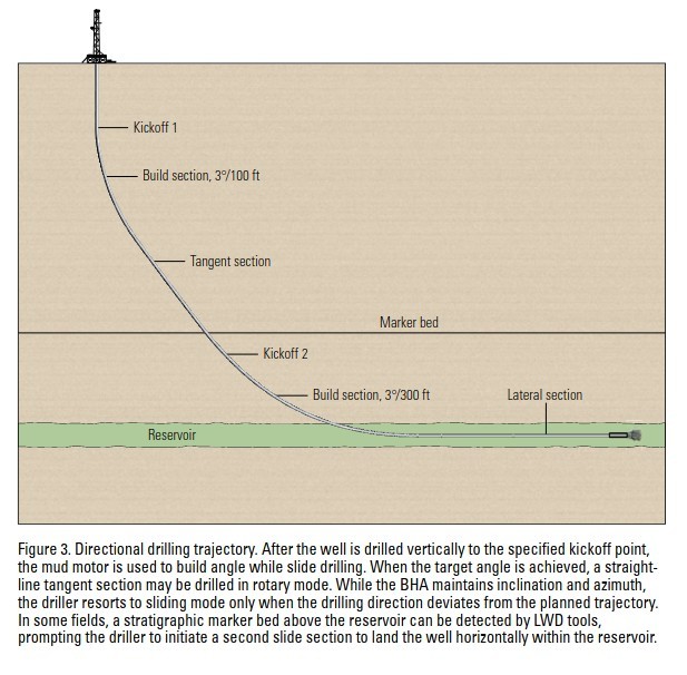
To initiate a slide, the driller must first orient the bit to drill in alignment with the trajectory proposed in the well plan. This requires the driller to stop drilling, pull the bit off-bottom and reciprocate the drillpipe to release any torque that has built up within the drillstring. The driller then orients the downhole mud motor using real-time MWD toolface measurements to ensure the specified wellbore deviation is obtained. Following this time-consuming orientation process, the driller sets the topdrive brake to prevent further rotation from the surface. The slide begins as the driller eases off the drawworks brake to control the hook load, which, in turn, affects the magnitude of weight imposed at the bit. Minor right and left torque adjustments are applied manually to steer the bit as needed to keep the trajectory on course.
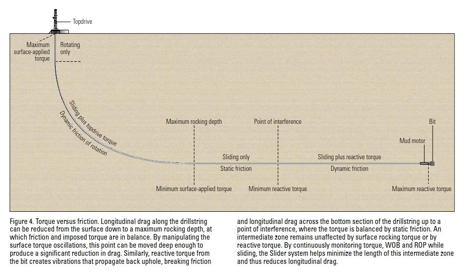
As the depth or lateral reach increases, the drillstring is subjected to greater friction and drag. These forces, in turn, affect the driller’s ability to transfer weight to the bit and control toolface orientation while sliding, making it difficult to attain. Torque from the topdrive rotates the drillstring from the surface down to a maximum rocking depth, where friction against the side of the hole prevents the pipe from turning. At the same time, as the mud motor turns the bit, it generates a reactive torque in the opposite direction. This torque is transmitted a short distance up the drillstring until it is overcome by friction at some point between the bottom of the wellbore and the BHA, referred to as the point of interference (Figure 4).
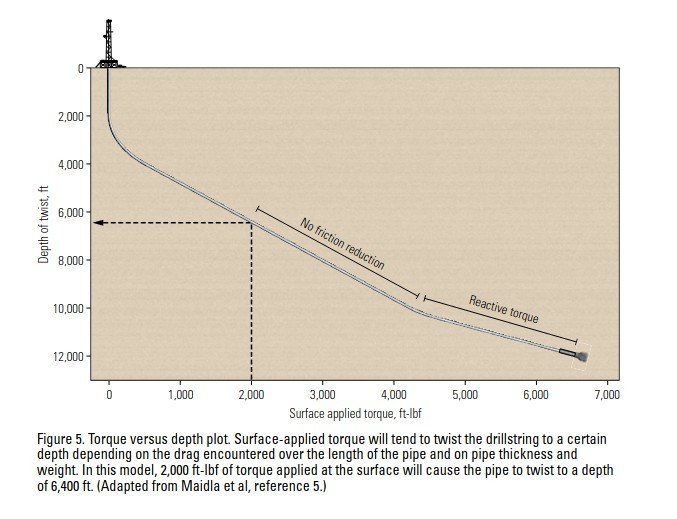
As the horizontal departure of a wellbore increases, so does the longitudinal drag of the drillpipe along the wellbore When weight is applied to the bit, torque at the bit increases. Torque is transmitted downhole through the drillstring, which turns to the right, in a clockwise direction. As weight is applied to the bit, reactive torque, acting in the opposite direction, also develops. This left-hand torque is transferred upward from the bit to the lower part of the drillstring.Between the depth where surface torque is overcome by friction and the point where reactive torque is overcome by friction, the pipe does not rotate. This section of drillstring, which has no tangential motion, moves by sliding only and is subject to static friction, which is greater than the dynamic friction of pipe in motion.The location of the point of interference varies with changes in the amount of reactive torque. To efficiently minimize the sliding interval between the depth of rocking and the point of interference while keeping the maximum rocking depth relatively constant, an automated control system must be used. The amount of surface torque supplied by the topdrive dictates in large part how far downhole the rocking motion will be transmitted. This relationship between torque and rocking depth can be modeled using conventional torque and drag programs (Figure 5).
https://www.slb.com/-/media/files/oilfield-review/04-slide-drilling-english
Fracking
Methane gas reserves are trapped rocks that are ideally- porous – the rock has open spaces (pores) between the rock grains
- permeable – the pores are interconnected
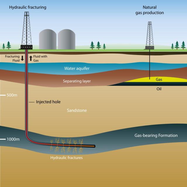
Fracking is a process that is done after the initial drilling ofthe well.
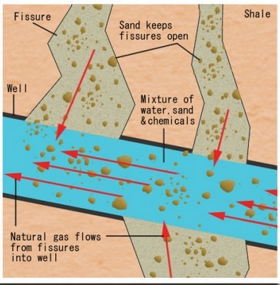
In the fracking process..
- sand is usually mixed with water and / or other (patented)
solvents and injected into the formation at high pressures. This
process creates cracks, or fissures, that the natural gas can seep
through
- or explosives may also be used to rupture the surrounding rock
and release the gas.
https://sites.suffolk.edu/alexakay11/2013/02/14/natural-gas-hydraulic-fracturing-hydro-fracking-21413/fracking-graphic/

