Diamond Drilling

Diamond Drilling - Exploration Drilling Methods
Diamond Core Drilling
RVC Drilling
Drill Sections
Drilling is the culmination of the mineral exploration process where the third dimension of a prospect, the subsurface geometry, is defined. Drilling provides most of the information for the final evaluation of a prospect and will ultimately determine if the prospect is mineable. Geochemical analyses of the drill samples provide the basis for determining the average grade of the ore deposit. Careful logging of the drill samples helps delineate the geometry and calculate the volume of ore, and provides important structural details. The two principle types of drilling are diamond core drilling and reverse circulation drilling (or RVC drilling).
Diamond Core Drilling
Diamond core drilling uses a diamond bit, which rotates at the end of drill rod (or pipe) (Figure 16 – 1). The opening at the end of the diamond bit allows a solid column of rock to move up into the drill pipe and be recovered at the surface. Standard core sizes are 7/8 inch (EX), 1 3/16 inch (AX), 1 5/8 inch (BX) and 2 1/8 inch (NX). Most drill rods are 10 feet long. After the first 10 feet is drilled, a new section of pipe is screwed into the top end, so the combination of pipes can be driven another 10 feet into the ground. The diamond bit is rotated slowly with gentle pressure while being lubricated with water to prevent overheating. The drill depth is estimated by keeping count of the number of drill rods.
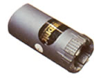
Figure 16 – 1. Diamond bit.
The driller listens to the drill very carefully to evaluate the condition of the drilling below. He will adjust the rotation speed, pressure and water circulation for different rock types and drilling conditions so as to avoid problems, such as getting the bit stuck or overheated. Highly fractured rocks (often encountered near the surface), in addition to the risk of a stuck bit, allow the fluids to escape, leading to overheating. The problem is minimized by injecting “drilling mud” (or sawdust or other materials) into the drill hole to “plug” the fractures and prevent escape of the fluids.
Inside the drill pipe is a “core tube”, which has a latching mechanism attached to a cable. At the end of each 10 foot run, the cable is used to winch the core tube containing the new rock core to the surface where it can be recovered. The drill core is stored in specially designed core boxes containing compartments to hold sections of the core. Standard core boxes are 2.5 feet long and contain four compartments, so ten feet of core can be stored in each box.
The drill core is first washed and logged by a qualified geologist, and then split in half to provide a sample for geochemical analysis. Since so much time, effort and money is expended to obtain the drill core, it is worthwhile to study and log the core very carefully. A standardized log form is used to log the core. The form has columns for each of the types of information which will be recorded, with tick marks indicating the footage. The information typically shown includes the recovery %, lithology, alteration, mineralization, rock quality data (RQD), and structural details. Although the strike and dip of planar features such as bedding, foliation, faults and veins is not known, the angle of these features with respect to the axis of the drill core axis is noted, because it still provides valuable information about the geometry of the features. Mineral testing may also be done, including testing for fluorescence (scheelite), testing for effervescence with dilute HCl (carbonate alteration), or mineral staining (feldspars or carbonates). Often the core will be photographed as well. The recovery % is the ratio of the actual core length compared to the drill interval indicated. Voids and fracture zones cause poor recovery. For example, if a drill run of 10 feet obtains 8 feet of drill core, the recovery is 80 %. The drill logs used to construct drill sections (cross sections showing the drill holes) which illustrate the subsurface geometry of the ore body. The current trend is to create drill logs in digital or spreadsheet format, which facilitates the construction of drill sections by computer.
Core splitting is done using a rock saw or an impact core splitter. There is always the problem of obtaining a representative split of the core. Great care must be taken to avoid this problem. Sometimes the entire core is analyzed to avoid this problem, but usually only if logging is extremely thorough. In some cases a series of small chips are collected along the length of the core to form a “skeleton core” for archiving purposes.
RVC Drilling
RVC drilling is fundamentally different from diamond core drilling, both in terms of equipment and sampling. One major difference is that RVC drilling creates small rock chips instead of solid core. Other major differences are in the rate of penetration and cost per foot. RVC drilling is much faster than diamond core drilling, and also much less expensive.
RVC drilling requires much larger equipment, including a high capacity air compressor. The compressor forces air down the outer space of a double wall pipe (Figure 16 - 2). The air circulates back up through the inner pipe carrying the rock chips, which are recovered at the surface. The chips travel at such high velocity they must be slowed down first, using a “cyclone”. The “return pipe” directs the chips to glance off the inside wall of the cyclone chamber, and then spiral downward to the bottom of the cyclone, loosing velocity in the process. The chips are collected continuously as the drill advances into the ground. Drill pipes used for RVC drilling are usually either 6” or 8” in diameter and 20 feet in length. Each pipe is extremely heavy and requires the use of a winch to lift and position over the drill hole.
 Figure 16 - 2. RVC double wall drill pipe (with tricone bit)
showing air path (from NEW ERA Engineering Corp).
Figure 16 - 2. RVC double wall drill pipe (with tricone bit)
showing air path (from NEW ERA Engineering Corp).RVC drill bits are also completely different from diamond drill bits. One type is called a “hammer bit”, named for the way it rapidly pounds and pulverizes the rock interface. This type of bit works well in dry drilling conditions (ie, above the water table) and in rock formations which are dense and hard. Below the water table, the water in the formation actually cushions the bit, making it much less effective at shattering the rock. Another type of drill bit, called a “tricone bit”, has three revolving cone-shaped grinders, which rotate together like the differential gears in a car transmission. Tricone bits are slower drilling in hard formations, but are very effective in soft formations and in wet drilling conditions.
Samples of drill cuttings are usually collected over five foot intervals. The large diameter of the drill hole creates a huge volume of material for each sample, which is typically “split” into a reasonable volume to handle and send to the lab for analysis. In dry drilling conditions (above the water table), a dry splitter is used (also know as a Jones splitter) (Figure 16 - 3). Usually a split of 1/8 of the total is collected. The Jones splitter is made up of tiers, each of which splits the sample in half. After the third tier split, 1/8 of the original total sample remains, which is collected in a bin or bucket. When the drill reaches the depth of the water table, rotary “wet” splitter is used (Figure 16 - ). The wet splitter spins around and splits the sample using a series of fins, similar to the fins in a turbine engine. Every other chamber directs material to a pipe which funnels the material into a bucket.
 Figure 16 - 3. Typical dry splitter samping (A) and wet splitter
sampling (B) arrangements.
Figure 16 - 3. Typical dry splitter samping (A) and wet splitter
sampling (B) arrangements. Small representative samples of the chips are collected continuously during the sampling process and placed in plastic boxes with compartments called “chip trays”. These are carefully observed and logged by a competent geologist. Of course some types of information, such as structural details, are not possible to obtain in the absence of solid rock. In spite of this disadvantage, much valuable information can still be obtained from the rock chips. For example, the chips are much easier to examine under a microscope. Testing of fluorescence and effervescence are easily accomplished.
Drill Sections
Drill data is interpreted by constructing “drill sections”, which show the drill holes in a vertical profile analogous to cross sections. Construction of the drill section begins in the same manner as a geologic cross-section, by creating a topographic profile. Then the “collar” locations (where the drill enters the ground) are plotted along the topographic profile. A vertical drill hole (plunge = -90 deg) will plot as a vertical line on the drill section, and angle drill holes are plotted showing the appropriate inclination. The length of the line(s) which illustrate the drill hole are determined by the scale of the drill section. For example, if the drill section scale is 1 inch = 10 feet, then a drill hole with a total depth (TD) of 100 feet will be 10 inches long.
Drill holes which are not situated exactly along the drill section line can be “projected” onto the plane of the drill section (within a reasonable distance) (Figure 16 – 4). The projection is done along a line perpendicular to the drill section line. If an inclined drill hole does not plunge directly into the vertical plane of the drill section, then its inclination on the drill section will appear as an “apparent dip”. The apparent dip angle is always less than the true dip. The apparent dip angle is a function of the true dip and the angle between the drill section line and the drill hole surface trace in a map view (Table 16 – 1).
If a drill hole intersects a tabular-shaped mineralized zone or rock layer at a 90 degree angle, then the thickness of the zone or layer seen in the drill core or recorded in the drill log represents the “true thickness”. If the drill hole intersects the zone or layer at any angle less than 90 degrees, then the thickness observed is called “apparent thickness”. The true thickness of the mineralized zone must be known in order to calculate the volume of the zone (Volume = length x width x thickness). If the dip of the mineralized zone is known, and the inclination of the drill hole is known, then the true thickness can be calculated using simple trigonometry.
Figure 16 - 4. Map showing the projection of several drill hole collar locations onto drill section line.
Table 16 – 1. Apparent Dip Angles as function of true dip and strike orientation.
Each drill hole on the drill section should show the name of the drill hole above and the total depth (TD) below (Figure 16 - 5). At this point, a decision is made as to which information will be shown. Typically each drill hole shows the intervals containing significant or ore grade values. Often this is done by highlighting or bracketing these intervals. Now the geologist may interpret the geometry of the ore zone by extrapolating between drill holes, which is a matter of connecting the upper and lower contacts of the zone from one drill hole to the next. The geology may be interpreted in different ways by different geologists (Figure 16 - 6). To help with the interpretation, additional drill sections may be constructed which show different aspects of the drill data. For example, another drill section may be constructed which shows a specific alteration or mineralization type.
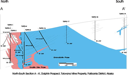
Figure 16 – 5. Drill section with ore intercepts and geology.
Figure 16 - 6. Two different interpretations of the same drill section (from SME Mining & Engineering Handbook).